


In this article
The standard single-mode fiber we are used to has one light-guiding core in the middle of a 125-micron glass cladding. Multi-core fiber, or MCF, places several cores inside that same cladding. A four-core MCF can carry four separate optical paths while keeping the outside glass diameter the same as a conventional fiber strand. This gives operators more capacity without requiring a larger fiber footprint inside the cable or conduit. In this article, I will dive into a little more dryer post. Lots of technical data about MCF.
This Is Not a High-Fiber-Count Cable
A high-fiber-count cable may bring 288, 864, or several thousand conventional strands into a data center. Each strand still has one core. The cable manufacturer packs more strands under the same outer jacket by using ribbon fiber and denser cable construction.
If you cut a four-core MCF and inspect the end face, you would see four core positions inside one common cladding. The distinction matters when ordering cable because a 288-count cable made from normal single-core fiber is not a 288-core MCF system.
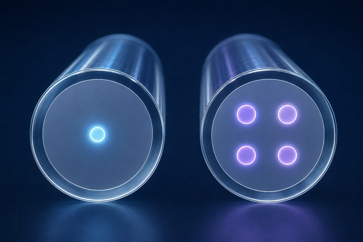
How Multi-Core Fiber Carries More Traffic
Each core in a weakly coupled MCF acts as its own channel. One core can carry a set of wavelengths while the next core carries another set at the same time. The fiber uses space-division multiplexing in addition to the wavelength-division multiplexing already common in today’s optical networks.
A four-core fiber does not make one 400G wavelength turn into 1.6T. The transmission system must send a separate signal into each core and receive each signal at the far end. If all four cores carry 400G, the strand has 1.6T of aggregate capacity, but the optics and supporting hardware still have to provide four 400G channels.
The 125-micron diameter matches the glass diameter used by standard single-mode fiber. Cable manufacturers can work with familiar coating sizes and much of the same cabling machinery. The familiar diameter does not make MCF interchangeable with a normal LC patch cord because the cores no longer sit at one common center point.
Light Into Multiple Cores
A normal transceiver sends light toward one centered core. A multi-core link needs a fan-in/fan-out device, often called a FIFO, or another optical interface that maps conventional single-core inputs to the individual cores. At the far end, another device separates those cores back into interfaces the transmission equipment can use. Think of this as a way to map light onto separate pathways and un-map them at the other end.
That hardware becomes part of the link budget. Every fan-in/fan-out device and connector adds insertion loss. Loss may also differ between cores, so an operator has to measure each spatial channel instead of treating the strand as one optical path.
Core position has to line up at every connection. A conventional fusion splice aligns fiber on the horizontal and vertical axes. MCF adds rotational alignment because the core pattern can be centered while the individual cores remain turned away from their matching positions. The ITU technical report on space-division multiplexing (warning: very dry reading) notes that MCF connections need precise angle alignment.
Crosstalk
Light in one core can leak into a neighboring core. We usually see this in dense muxes, but it can be an issue with MCF. That inter-core crosstalk raises interference at the receiver and reduces the margin available for modulation. Core spacing and refractive-index design affect how much energy crosses between channels. Wavelength and link length also greatly affect crosstalk.
Bending and twisting also affect crosstalk. A fiber can meet its optical targets on a spool and behave differently after it is installed in a cable. A tight bend inside a splice enclosure can alter the crosstalk again. Qualification testing must include cable design and installed bend radius. This is nothing new in the fiber world, just amplified at scale.
Weakly coupled MCF keeps each core isolated enough that the receiver can process it as an independent channel. Other designs allow more coupling and use MIMO digital signal processing to separate the signals. That supports more spatial channels, but the receiver becomes more complex.
Four-Core MCF Is All the Rage
Four cores can fit inside a 125-micron cladding with enough spacing to control the crosstalk. The outer cores also need enough glass between them and the edge of the cladding. That balance gives equipment manufacturers a practical target that remains close to what a standard single-mode fiber is like. In March 2025, ITU-T Supplement 87 identified weakly coupled MCF with a 125-micron cladding as the first priority for standardization. The plan also calls for optical properties that remain compatible with G.65x.
The capacity potential is substantial. NICT demonstrated 319 Tbps across 3,001 kilometers of 125-micron four-core fiber way back in 2021. The test used 552 optical carriers across more than 120 nm of spectrum, with separate signals launched into each core. It proved what the glass and transmission system could carry, but it was not a standard optic that could be installed in an existing router.
Higher core counts are possible. Sumitomo developed an eight-core, 125-micron fiber for short-reach O-band interconnects and placed 12 MCF strands inside a 3 mm cable. Packing more cores into the cladding gives the designer less room to control crosstalk and confinement loss.
Where MCF Fits in a Data Center
A data center pathway has a fixed amount of tray and conduit space. If four spatial channels can travel through one coated strand, a trunk can carry more optical paths without making the cable proportionally larger. That can help on a campus route where pulling another cable through the existing conduit is difficult.
In 2025, an NICT deployment used four-core MCF strands inside a 3 mm cable. The cable provided the equivalent of 32 conventional single-core fibers inside one 3 mm cable. It carried multiple uncompressed 8K video signals for 300 meters through limited building pathways.
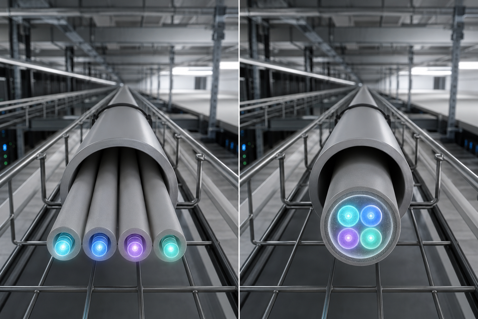
The same density could become useful between data center rows or separate buildings as 400G and 800G links consume more optical paths. MCF does not reduce the number of transceiver lanes the equipment needs. It reduces the amount of glass and cable space used to carry those lanes between endpoints.
Multi-Core Fiber Does Not Provide Path Diversity
Four cores inside one cladding still share one physical strand. A backhoe cut can take down every core at once. A broken connector or bad splice can do the same. MCF increases channel density, but it does not provide route diversity. It also increases repair complexity. Now you have many more cores to deal with during a cut. This density adds another layer to troubleshooting.
Stocking ordinary LC jumpers will not repair an MCF connector or replace a failed fan-in/fan-out unit. An operator evaluating the technology needs to price the termination hardware with the cable. The correct test gear and splicing tools are specialized, which adds cost to your fiber plant crews.
Is Multi-Core Fiber Ready for Production?
The 125-micron footprint gives MCF a path toward existing cable plants, but the connector and splicing ecosystem is still developing. The ITU published its first SDM standardization framework in 2025. That work covers the fiber along with the test and interconnection methods needed around it.
Conventional single-mode fiber and high-fiber-count ribbon cable remain easier to buy and repair for most ISP and data center networks. MCF becomes more interesting when conduit space limits the number of optical paths that can be installed. The operator then has to decide whether the added density is worth the specialized interfaces and field procedures required at each end.
j2networks family of siteshttps://j2sw.com
https://startawisp.info
https://indycolo.net
#packetsdownrange #routethelight
Discover more from Justin Wilson (j2sw)
Subscribe to get the latest posts sent to your email.