Have you ever looked at a data center marketing slick and wondered what N, N+1, 2N, and 2(N+1) actually mean? The main thing they tell you is how many components can fail before the system drops below the capacity needed to support the load.
When I evaluate a data center, I want to know what the redundancy rating covers if they are advertising one. I also want to know what happens when a UPS module is offline and another component fails. Let’s get into what they mean in this post.
N Is the Capacity Required to Carry the Load
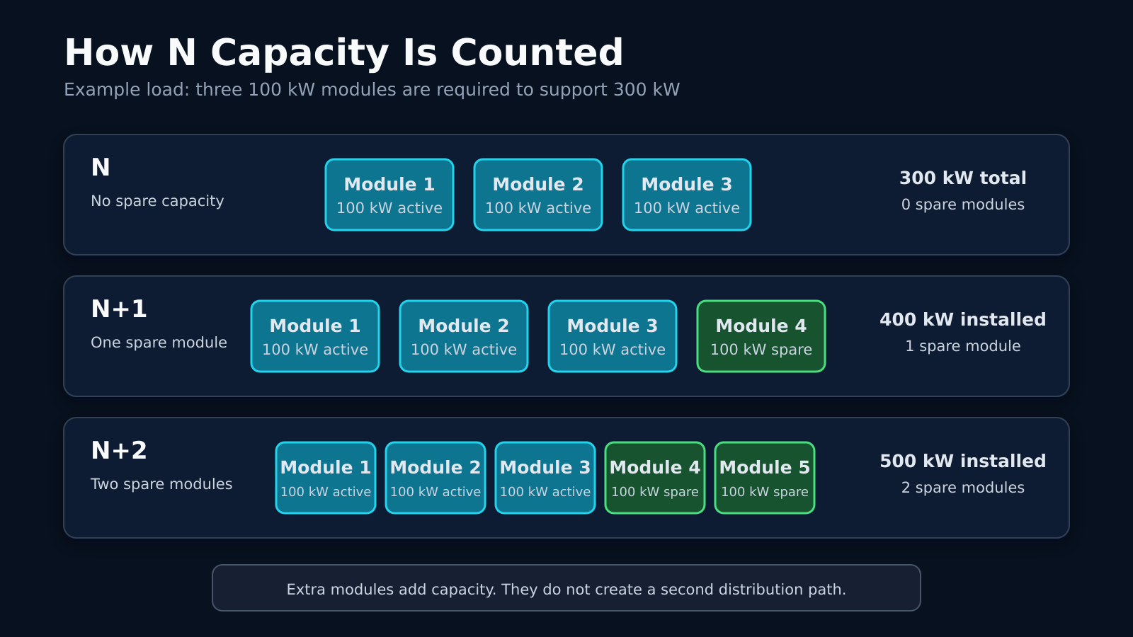
A UPS plant may need three 100 kW modules to support a 300 kW design load. Those three modules represent N. All three must remain available for the plant to carry its full rated load. If one module stops working, only 200 kW remains. The facility must reduce the load or transfer it to another system. An N design has enough equipment for normal operation, but it has no spare capacity.
The same calculation applies to cooling. If four cooling units are required to hold the room at its target temperature, those four units are N. Losing one unit leaves the room below its required cooling capacity.
N+1 Adds One Spare Component
Add a fourth 100 kW UPS module to the 300 kW plant, and the system becomes N+1. Three modules carry the load. The fourth provides enough capacity for one module to fail or undergo maintenance.
N+1 works well when the failure stays inside the group of UPS modules. It does not help if all four modules feed one output panel and that panel fails. The spare module has no alternate path to the distribution panel.
I also want to know how heavily the plant is loaded. A four-module system may have been N+1 when the load was 250 kW. If the load grows past 300 kW, the fourth module is no longer a full spare.
N+2 Provides Two Spare Components
An N+2 plant would use five 100 kW modules to support the same 300 kW load we talked about. Two modules can be unavailable while the other three continue carrying the load. That gives the facility room for a maintenance event and a second module failure. Murphy’s law will come into play at least once.
Cooling plants often use this type of design where repairs can take time. One chiller may already be disassembled when another develops a problem. The remaining chillers still need enough capacity to keep the room within its temperature limits.
N+2 still describes component capacity. Five chillers connected to one failed control system may all stop together. The shared equipment has to be included when reviewing the failure path.
2N Uses Two Complete Systems
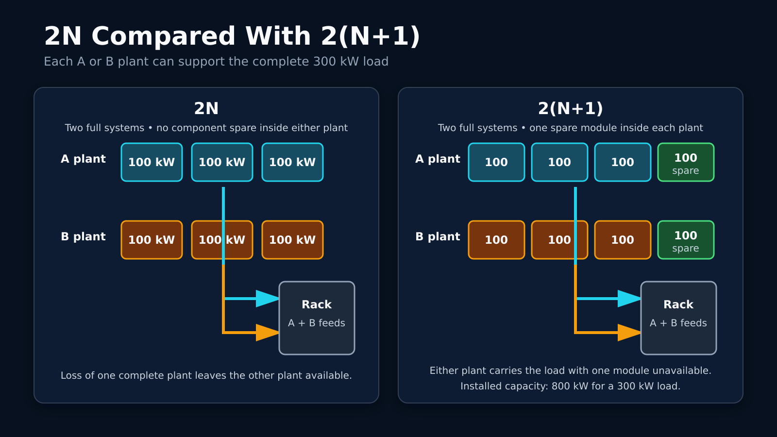
A 2N design provides two systems that can each support the full load. A 300 kW facility load would have a 300 kW A system and a separate 300 kW B system. Either side can carry the load without help from the other.
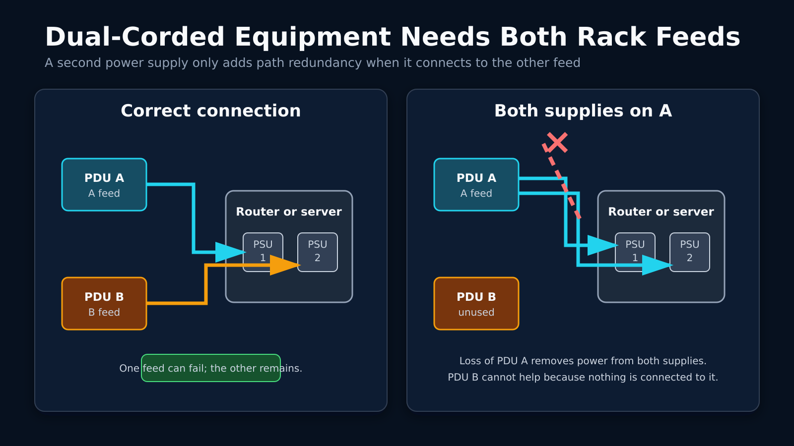
At the cabinet, a dual-corded router can connect one power supply to A and the other to B. If the A path goes offline, the second power supply keeps the router running from B. This requires both paths to have enough capacity for the load after the transfer.
The facility’s definition of the 2N rating matters. A facility may have two complete UPS plants, while both plants depend on the same generator bus. That is 2N at the UPS level, but a generator-bus failure can still remove both power paths.
2N+1 Depends on Where the Spare Is Installed
A 2N+1 design starts with two complete systems and adds one spare component. The extra component may be another UPS module or cooling unit. Its value depends on which side can use it.
A spare UPS module connected only to the A system cannot replace a failed module on B. Some facilities use switchgear that allows the spare to support either side. Others use 2N+1 to describe a different arrangement, so the label can be unclear without a drawing.
I would ask the facility to identify the extra component on its single-line diagram. The maintenance procedure should explain how that component enters service. It should also state whether connecting the spare places A and B onto common equipment.
2(N+1) Gives Each Side Its Own Spare
A 2(N+1) plant has two complete systems, and each system has its own spare component. In the 300 kW example, the A plant would have four 100 kW modules. The B plant would have another four. Either side can support the full load with one module unavailable. The facility can service one A-side module without using the B plant. If the entire A system fails, B can carry the load while retaining its own spare module.
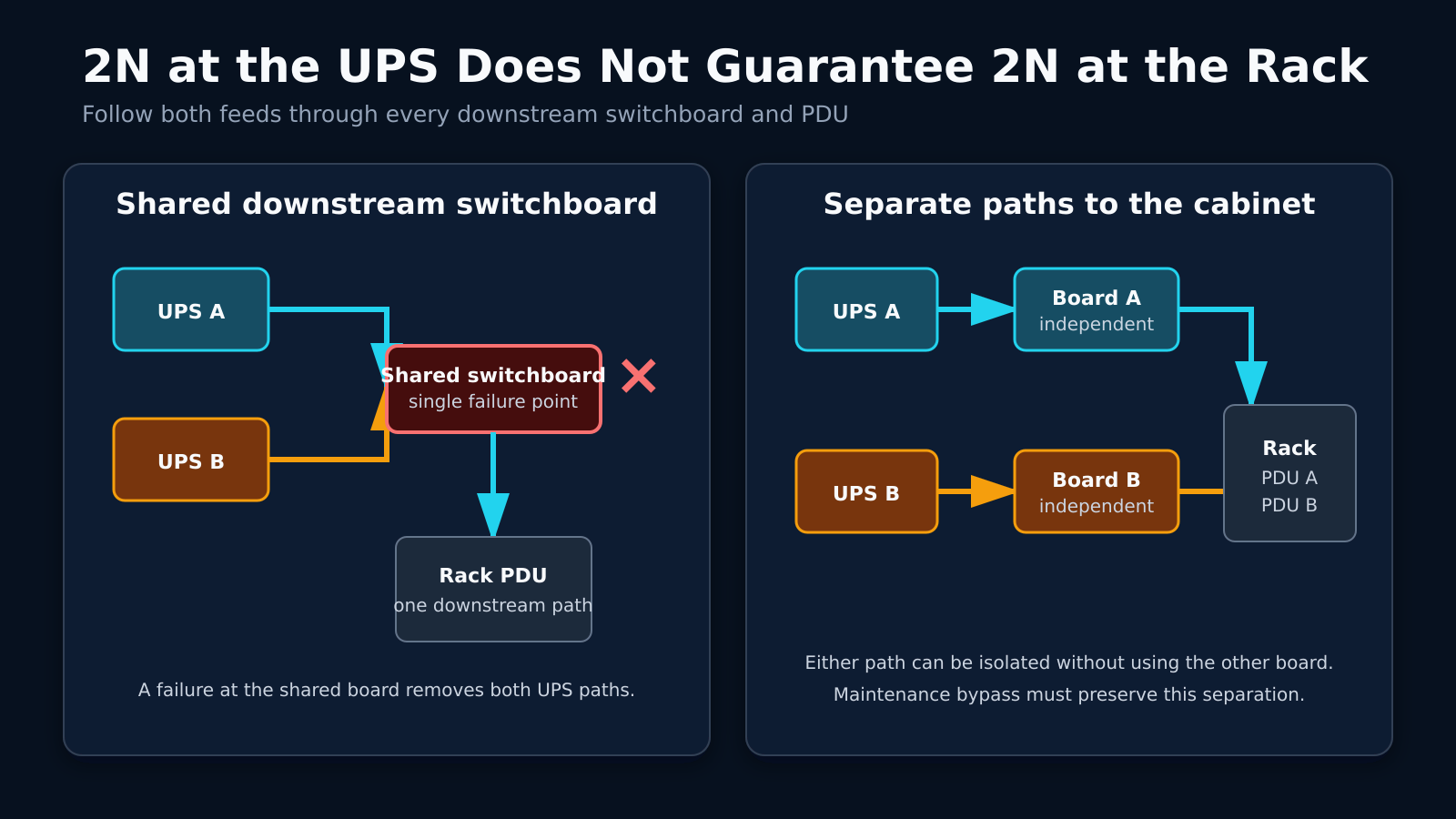
The cabinet distribution still needs two separate paths. Two N+1 UPS plants feeding the same downstream panel leaves that panel as a single failure point. A and B need to be fully separate in terms of path and physical location.
Follow the Power Path to the Cabinet
Power reaches the UPS only after passing through upstream electrical equipment. It leaves the UPS through more electrical switchgear before reaching the cabinet. A shared component along that path can remove power from both feeds.
Maintenance bypass equipment deserves a close look. During normal operation, A and B may follow separate paths. A UPS maintenance procedure may place both sides onto a shared bypass source. I want to know where the paths cross, which breakers are common, and the path down to the cabinet level.
Dual Feeds Need the Right Cabinet Connections
A dual-corded router normally has one power supply connected to the A PDU and the other connected to B. Plugging both supplies into A leaves the router dependent on one feed. The second power supply only protects against a power-supply failure.
Single-corded equipment needs another method to use both feeds. A rack-mounted automatic transfer switch can select between A and B, but every connected device now depends on that switch. Its capacity must support the full connected load after a transfer. That transfer now becomes a single point of failure. Keep going down the rabbit hole until you get to the end.
I also check circuit loading on both feeds. If the rack normally splits its load between A and B, either circuit may receive more load after a failure. The surviving breaker needs enough capacity to hold without tripping. You, as the tenant, also need to be mindful of not loading your circuit beyond 80% capacity.
Cooling Redundancy Needs looked at too
A room may need four cooling units to handle its heat load. Installing a fifth makes the unit count N+1. One unit can stop while the other four continue moving enough heat out of the room. Those five units may still depend on one chilled-water loop. A broken pipe can remove cooling from every unit attached to that loop. The extra cooling unit does not help when it has no chilled water.
I want to know whether the redundancy rating applies to the units in the room or the complete cooling plant. Pump capacity matters during a failure. Pipe isolation also determines whether technicians can repair one section while the other section remains in service.
Maintenance Can Reduce the Available Redundancy
An N+1 UPS plant can normally lose one module and continue supporting the load. During maintenance, the spare may already be offline. A second module failure would leave the plant below N.
Switchgear maintenance can be more complicated because a breaker or bus may serve several UPS modules. The facility may need to move the load to bypass power before opening the equipment. That transfer can place the rack onto a path with less redundancy.
I want the facility to walk through a real maintenance event. If the A-side switchboard needs service, which equipment carries the rack? The answer should include what happens if another component fails while that work is underway.
Shared Equipment Can Defeat Redundant Components
Two generators may depend on the same fuel pump. If that pump fails, neither generator receives fuel. The second generator does not provide another usable source.
Cooling controls can have the same weakness. Several cooling units may depend on one controller that starts the pumps. A controller failure can stop the complete plant even when every cooling unit still works.
N Ratings and Data Center Tiers Are Not the Same
N terminology describes equipment capacity and arrangement. A data center Tier rating covers more of the facility design, including maintenance and failure behavior. A 2N UPS plant does not give the complete building a Tier certification.
A facility may also use redundant systems without holding a formal certification. I would not reject the building based on that fact alone. I would review the power path and ask how the facility handles a real component failure.
Questions I Would Ask the Data Center
- Which systems are N+1, N+2, or 2N?
- Does the rating cover the current load or the full design load?
- Where do A and B share equipment?
- Can either cabinet feed carry the full rack load?
- What happens when one component is already under maintenance?
- Can each switchboard be isolated without dropping customer power?
- Does the cooling rating cover the plant or only the room units?
- Can I review the electrical single-line diagram?
- When was the last transfer test performed under load?
Before installing equipment, I want to know how both feeds connect to the cabinet. I also want to understand what changes in the power path during maintenance. The single-line diagram and the failure procedure provide more useful detail than an N+1 or 2N label by itself. While you may not need all of this redundancy, knowing your failure points helps in many situations. It speeds up troubleshooting. It lets you know your exposure if something were to go wrong.
j2networks family of siteshttps://j2sw.com
https://startawisp.info
https://indycolo.net
#packetsdownrange #routethelight
Discover more from Justin Wilson (j2sw)
Subscribe to get the latest posts sent to your email.