If you work around data centers and high-density builds, you have probably heard the term “Multi-Core Fiber” thrown around. People use it in a few different ways. Sometimes, it means a new fiber trunk that comes into a cabinet as a single cable and breaks out into dozens or even hundreds of fibers. That setup can take the place of a big bundle of duplex patch cords between racks.
A lot of folks call this multi-core fiber, but in most data center discussions, the right term is multi-fiber cable or high-fiber-count cable. Each strand in the cable still has its own glass core and cladding. True multicore fiber is something else entirely, where several optical cores share the same cladding. That’s a different technology, and I’ll cover it in a future post.
This difference actually matters when you’re ordering parts. A standard MPO trunk will not connect to optics built for true multicore fiber. Most data centers use regular single-core strands bundled together, so that’s what I’ll focus on here.
What Is Inside a Multi-Fiber Cable?
A basic duplex fiber link uses two strands. One strand carries the transmit signal in one direction, while the other carries traffic back. Ten duplex links therefore require 20 strands unless the optics use bidirectional wavelengths on the same strand.
A multi-fiber trunk just puts all those strands under one outer jacket. The fibers might be grouped into ribbons or smaller bundles. How the cable is built changes how it bends and how you get to each fiber, but each strand is still its own optical path.
Fiber count does not tell you whether the cable is single-mode or multimode. A 24-fiber trunk could contain OS2 single-mode fiber for longer links. The same count could use OM4 multimode fiber for short switch connections inside the data center.
MPO and MTP Connectors
A lot of data center trunks end with an MPO connector instead of a bunch of separate LCs. MPO is a rectangular connector that holds several fibers in one ferrule. MTP is a specific MPO design from US Conec, so people use the names together, but they aren’t the same thing.
This connector saves panel space since one connection can carry several optical lanes. That density is handy when you’re tight on cabling space in the data center.
An MPO trunk can land in a cassette that has several LC duplex ports, or it can connect to an optic that uses parallel fibers.
You have to match the fiber count to what you’re doing. MPO-12 has 12 positions, but a typical 40GBASE-SR4 or 100GBASE-SR4 link only uses eight—four to transmit, four to receive, and the rest sit unused. Newer 400G and 800G optics might use MPO-16 since they need eight transmit and eight receive lanes.
How Parallel Optics Use the Fibers
A duplex LC optic can stack multiple wavelengths on a single fiber pair. Parallel optics do it differently—they split the signal across several fibers. Each lane carries part of the total bandwidth, and the switch pulls them together into one Ethernet port.
Take Cisco’s 400GBASE-DR4 optic as an example for single-mode. It uses four transmit fibers and four receive fibers through an MPO-12. Each lane does 100 Gbps, so you get a 400G link across eight active strands. You can see how fast you start using up fiber strands.
Multimode optics work the same way for short runs. Cisco’s 400G SR8 module uses eight fiber pairs through an MPO-16, with each fiber doing 50 Gbps. An 800G VR8 optic also uses eight pairs, but each lane does 100 Gbps.
This hits the cable plant pretty hard. A rack with sixteen 400G SR8 links eats up 256 active fiber strands. Preterminated MPO trunks help keep all those strands together and cut down on the number of connectors you have to deal with in the tray.
Breakout Links
A high-speed switch port doesn’t always connect to another port at the same speed. For example, a 400G port might break out into four 100G interfaces. The switch handles the breakout, and the cable splits the optical lanes to the right ports. Aggregation is a big reason for this—it means you don’t need expensive switches everywhere.
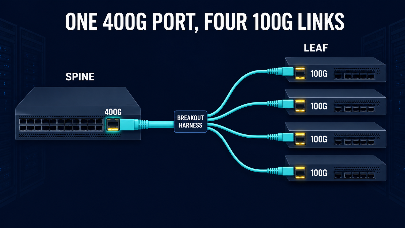
You might have one MPO connector leaving the spine switch and splitting into four duplex LC pairs for the leaf switches. Or you might use an MPO-to-MPO harness if the lower-speed optics also use parallel lanes. The harness you need depends on the optic, so just knowing the connector shape isn’t enough when you order the cable.
Breakouts also change how things get labeled. The switch config might call the child ports Ethernet1/1/1 through Ethernet1/1/4, but the harness could use a different label. If those don’t match, tracking down a failed link can take a lot longer. More cables means more labeling to keep straight.
What is Base-8 and Base-12?
Older structured cabling systems often use groups of 12 fibers because MPO-12 became a common trunk interface. Parallel Ethernet standards based on four transmit and four receive lanes only use eight of those fibers. The other four positions may remain dark unless a cassette or conversion module rearranges them for another service.
Base-8 systems group the cable use around eight active fibers. That maps cleanly to SR4 and DR4 optics, so an operator does not waste 4 of the 12 strands. Base-12 still works, but the migration plan needs to account for unused fibers and any conversion hardware.
Neither layout supports every future optic by default. A 400G SR8 optic needs 16 active fibers, while a 400G LR4 optic uses one duplex LC pair because it carries four wavelengths over two strands.
Polarity Can Stop a Link from Coming Up
Every transmit lane has to line up with a receive lane. With a regular duplex LC patch cord, that’s easy if it does not work. You just cross the connectors. MPO connectors handle a bunch of positions at once, so you need a set polarity method from end to end. MPO systems usually use Type A or Type B parts. Type C is out there too. Each method maps fiber positions differently. Mixing up trunks and cassettes from different methods can make troubleshooting a real headache as you scale up.
Connector pinning is another thing to watch for when you order. MPO connections use a pinned connector on one side and an unpinned one on the other to line things up. Two pinned connectors won’t mate, so you need to call out gender and polarity before you order the trunk.
Loss Budget and Cleaning
An MPO connector exposes a bunch of fiber ends in one ferrule. Dust on just one spot can knock out a single lane, even if the rest are fine. The interface can stay down because Ethernet needs every lane to meet the optic’s receive range.
Every cassette and connector adds insertion loss. If your path goes from the switch to a patch panel, across a trunk, and through another cassette, you can eat up more of your optical budget than with a direct cable. You need to run the loss numbers based on the optic spec and how many connections you actually have. Every connection adds loss.
One power reading doesn’t prove every lane has the right loss or polarity. You should check polarity and the end-face condition, and your test record needs to show each fiber position so you can tie a fault to a specific lane later. Picture trying to troubleshoot a bundle of 400 or more cables after install.
Diversity vs Capacity
A 144-fiber trunk gives you a lot of capacity, but every strand is in the same jacket and tray. One cut can take out all 144 fibers. Putting A and B switch links on different fibers in the same trunk doesn’t give you a separate path.
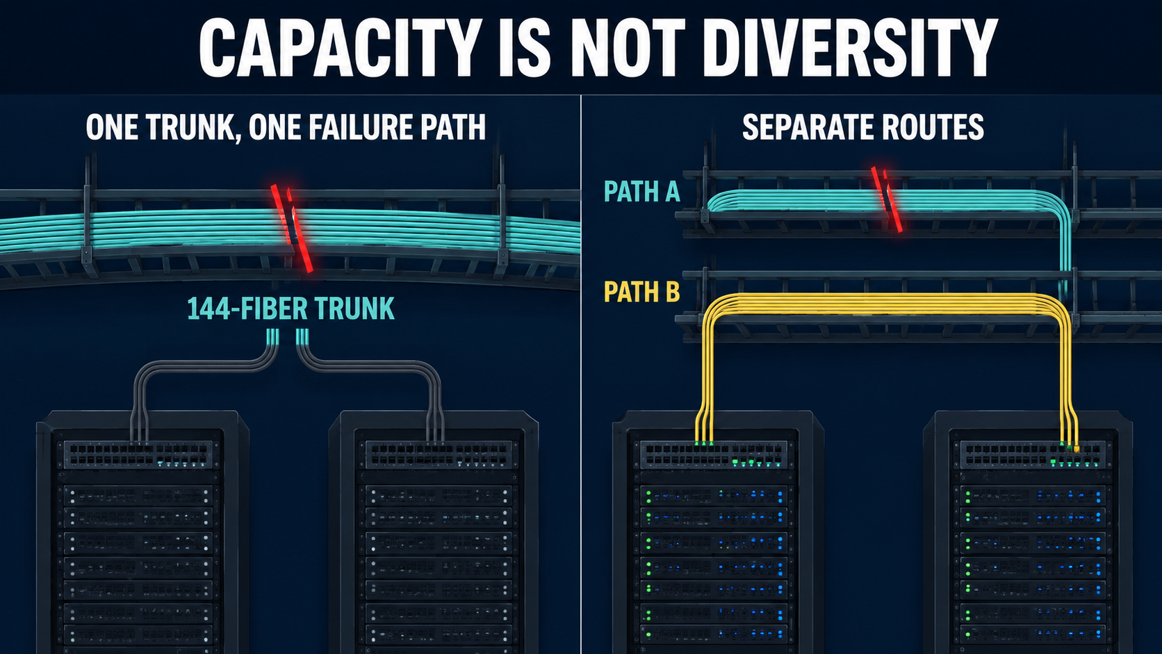
If you want real redundancy, you need separate cable routes in case a single cut is part of your failure model. That could mean different trays in the room and separate building entrances. Patch-panel labels should show the route, since strand numbers alone don’t prove diversity. You still need spare fibers so you can move around a damaged strand or add a new circuit without pulling new cable.
Hope this helps
j2networks family of siteshttps://j2sw.com
https://startawisp.info
https://indycolo.net
#packetsdownrange #routethelight
Discover more from Justin Wilson (j2sw)
Subscribe to get the latest posts sent to your email.