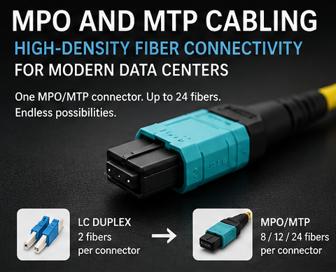
If you have spent any time in a modern data center, you have probably seen those wide, flat ribbon-style fiber connectors that look nothing like a standard LC or SC patch cord. Those are MTP and MPO connectors, and they are worth understanding because they show up everywhere high-density fiber is involved.
What is MPO and MTO?
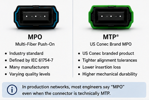
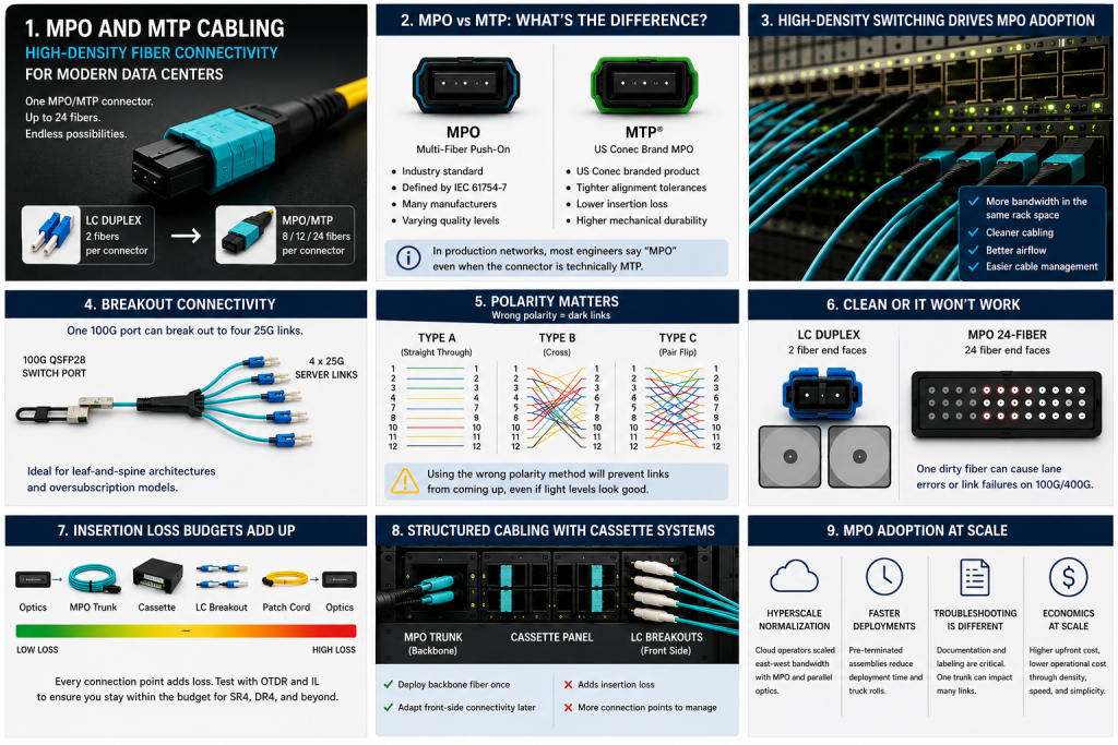
MPO stands for Multi-fiber Push On. It is a connector type defined by IEC 61754-7. The connector houses multiple fibers in a single small tube. This is typically 8, 12, 16, or 24 fibers, depending on the assembly.
MTP is a brand name. US Conec developed it as a higher-performance version of the MPO connector. MTP connectors meet and exceed the MPO standard, which means an MTP connector is compatible with an MPO port. The two terms get used interchangeably in the field, but technically, MTP is a specific product, and MPO is the standard. When a vendor says MTO, they usually mean the same thing, and the letter is just getting swapped in conversation or documentation. The actual standard you will see on spec sheets is MPO.
The Physical Connector
MPO connectors have built-in alignment pins. One end of a cable assembly is the male connector with pins, and the other is the female connector without. This matters when you are connecting trunk cables to cassettes or adapters because pinned and pinless ends have to mate correctly. Getting it wrong does not damage anything, but the light will not pass correctly, and you will get high insertion loss.
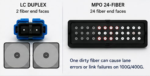
The ferrule holds all the fibers in precise positions. Because you are dealing with multiple fibers in one small ferrule, cleanliness and polish quality are critical. Any contamination on an MPO ferrule can take out multiple fiber paths at once, rather than just one, as with a standard LC connector.
How These Cables Get Used
MPO cables serve two main roles in the data center: trunk cables and breakout cables.
Trunk cables are point-to-point runs between patch panels or cassettes. You pull an MPO trunk from one rack to another and terminate it at each end into a cassette. The cassette converts the MPO connection on the back to individual LC ports on the front. This is the most common structured cabling approach, allowing you to pre-terminate all your fiber runs.
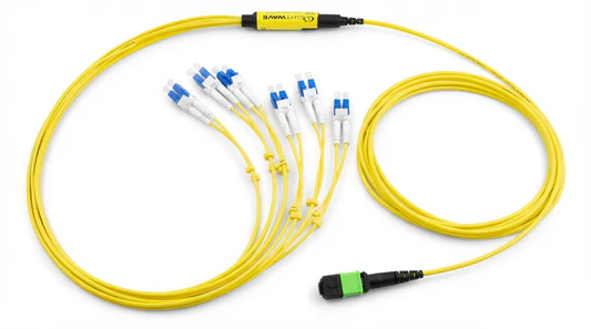
Breakout cables, sometimes called harness cables or fanout cables, take one MPO connector on one end and split out to individual duplex connectors on the other. A 12-fiber MPO to 6x LC duplex breakout is a typical example. These are useful when you need to connect directly to transceivers without going through a cassette system.
Polarity
Polarity is where MPO cabling gets complicated. The basic problem is that light needs to enter a transmitter and exit a receiver on the other end. With duplex LC fiber, it is simple: just flip the connector. With 12-fiber MPO, you have 12 fibers in specific positions, and those positions must line up correctly end to end.
TIA-568 defines three polarity methods: Method A, Method B, and Method C. Each one handles the fiber position mapping differently. The short version is that you need to plan your polarity scheme before you install anything and stick with it throughout the infrastructure. Mixing methods creates connectivity problems that are a pain.
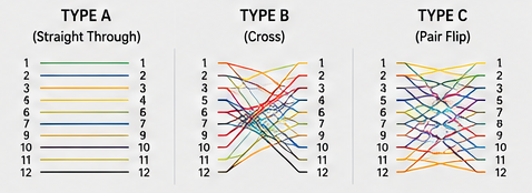
Method B is common in structured cabling systems because it uses a straight-through trunk cable where position 1 on one end maps to position 1 on the other. The polarity flip happens inside the cassette. Most data center cassette systems are designed around Method B.
Connector Polish Types
MPO connectors come in two common polish types: UPC (Ultra Physical Contact) and APC (Angled Physical Contact), just like you are used to doing with other fiber. APC connectors have an 8-degree angle on the ferrule face, which reduces back reflection. APC MPO connectors are green, and UPC are beige or off-white, following the same color convention as duplex fiber. APC is preferred for long runs or wavelength-sensitive systems. UPC is the default for most data center applications.
Where do we see this?
In a leaf-and-spine fabric, the high-density uplinks between leaf and spine switches drive the need for MPO cabling. A 400G port using DR4 optics uses a single 8-fiber MPO. Running dozens of these uplinks from a single switch makes MPO trunk infrastructure the only practical option.
Hyperscalers and large colocation providers pre-terminate their entire fiber plant with MPO trunks so moves, adds, and changes happen at the cassette layer without ever touching the infrastructure cables. This reduces installation time and keeps the fiber plant clean and organized.
Some Common Mistakes
Mixing MTP and MPO hardware from different vendors without verifying their compatibility specifications can cause insertion loss issues. While the standards say they should be compatible, ferrule tolerances vary and some combinations perform poorly.
Not inspecting and cleaning MPO connectors before mating them is probably the most common cause of bad links. An MPO connector needs a proper MPO cleaner, not a standard stick cleaner. The ferrule geometry is different.
Pulling MPO trunk cables without paying attention to the minimum bend radius damages the fibers inside. MPO trunks look robust, but the individual fibers are still glass.
j2networks family of sites https://j2sw.com https://startawisp.info https://indycolo.net #packetsdownrange #routethelight
https://j2sw.com
https://startawisp.info
https://indycolo.net
#packetsdownrange #routethelight
Discover more from Justin Wilson (j2sw)
Subscribe to get the latest posts sent to your email.