
If you’ve ever wondered how the capital I Internet actually works, you’re not alone! At its core, the Internet is a network of networks, and the way these networks connect has a big impact on the speed, cost, and reliability of our online lives. In this post, I’ll walk you through the basics of interconnection, peering, and transit—what they mean, how they differ, and why they matter. We’ll also explore the important role of Internet Exchange Points (IXPs) in improving peering efficiency. Along the way, I’ll share both the technical and business perks of peering, explain the main types of peering arrangements (public, private, and remote), and touch on some common BGP routing considerations like traffic engineering and route filtering. To bring these ideas to life, I’ll use Fiber Data Internet Exchange (FD-IX)—a Midwest-based IXP where I’m a Managing Partner—as a case study.
Interconnection vs. Peering vs. Transit
Before diving into IXPs and peering, it’s important to clarify the fundamental concepts of interconnection, peering, and transit, and how they relate to each other:
Interconnection: The Network-of-Networks
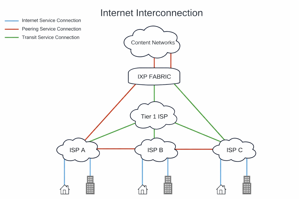
Interconnection refers to the process by which autonomous networks (ASNs) are linked together to exchange traffic In essence, interconnection is the broad concept of networks connecting so that data generated in one network can reach another efficiently. This can occur in various forms (peering or transit being the primary models), but the ultimate goal is the same: to ensure that any two points on the Internet can communicate, ideally with low delay or loss. Interconnection is the backbone of the Internet’s “network of networks” design.
Peering: Settlement-Free Direct Exchange
Peering is a common, often friendly way for two (or more) networks to connect and exchange traffic directly, without a middleman and usually without payment. In a peering arrangement, each network helps carry the other’s traffic to and from its own customers (and sometimes even those customers’ customers), but doesn’t send it out to the wider Internet. Peering is often free of charge (sometimes called bilateral peering when only two groups are involved), or involves minimal costs—unlike transit arrangements. The main idea is simple: both networks benefit by making things faster and more efficient for each other users, all while keeping costs down and avoiding extra steps through third-party providers.
Peering can occur either privately or at shared exchange points (more on public vs. private peering later). Large ISPs, content providers, cloud providers, and CDN operators frequently peer with each other to deal with high traffic volumes more efficiently. For example, instead of a streaming service’s data tromboning through multiple transit ISPs to reach a local broadband carrier, the two networks might peer at an exchange, handing off traffic at a nearby point and reducing round-trip time. Peering relationships do require mutual agreement (and sometimes a formal peering policy), but often they are established once traffic volumes between two ASes become significant enough to warrant direct exchange.
Transit: Paid Upstream Connectivity
Transit is a complementary concept to peering. In a transit relationship, one network pays another network (a transit provider, usually a larger ISP) for access to the entire Internet beyond its own network. The transit provider carries the paying customer’s traffic to any destination on the Internet that it doesn’t reach via its own network or peers. Essentially, buying IP transit from an upstream gives a network global reach – the transit provider will route your traffic to parts of the Internet that you can’t reach via direct peers. I did an article a while back explaining the differences.
In transit agreements, typically a customer network pays an upstream provider a recurring fee (often based on bandwidth, e.g. per Mbps of usage or a flat rate for a commitment) and in return the provider announces the customer’s routes to the rest of the Internet and forwards the customer’s traffic on. Transit is a paid service and usually comes with an SLA and the benefit of simplicity: the customer doesn’t have to manage many bilateral peerings; they rely on the transit ISP’s routing. Smaller ISPs or networks often start with transit because it instantly connects them to everywhere, whereas peering must be established network by network.
Peering is like a handshake to exchange traffic directly with specific networks for mutual benefit, whereas transit is like paying an ISP toll to carry your traffic to any destination you can’t reach via those handshakes. Both are forms of interconnection – just with different scopes and economics. The table below highlights some key differences:
| Aspect | Peering (Settlement-free) | Transit (Paid) |
|---|---|---|
| Financial Model | Typically settlement-free or minimal cost (often just a shared IXP port fee). | Paid service – customer pays provider per Mbps or GB for reachability. |
| Scope of Reach | Limited to routes of peering partners (only each other’s networks and customers). | Full global Internet reach (provider routes to all prefixes not on customer network). |
| Traffic Exchange | Reciprocal: each network carries only its own and its customers’ traffic for the other – no third-party transit. | One-way service: provider carries customer’s traffic to third-party destinations and vice-versa. |
| Cost & Usage | Fixed port costs, not usage-based; economical for large volumes (unit cost drops as traffic exchanged grows) | Metered or tiered costs; can become expensive at scale despite falling transit prices (must weigh vs. peering cost). |
| Performance | Often better latency & throughput due to direct route (fewer hops). Networks can engineer traffic for optimal paths. | Potentially longer paths through intermediate ASes; more hops can mean higher latency. Performance is at the mercy of provider’s routing decisions. |
| Control | High control: networks can selectively announce routes, apply custom routing policies with each peer (more granular traffic engineering). | Less control: the transit provider largely governs routing once traffic is handed off (limited policy control beyond local preferences). |
| Reliability | Increases redundancy: multiple peering links diversify paths (if one peer has issues, others are unaffected). Typically no contractual SLA, but diversity can improve resilience. | Transit providers often have SLAs, but if all traffic funnels through a few upstreams, those become single points of failure (multi-homing to multiple transit ISPs mitigates this). |
| Typical Use Cases | Heavy traffic between specific networks (e.g. content provider and ISP) where cost and latency savings justify direct exchange. Common among Tier-1/2 ISPs, CDNs, large content or cloud services. | Essential for reaching the broader Internet beyond your peers. Used by smaller ISPs, enterprises, any network needing global reach or easy scalability without managing many peers. |
As you can see, peering is often chosen when there’s a lot of traffic or an important connection, since it helps save money and boosts performance. On the other hand, networks use transit to make sure they can reach everywhere easily. Most networks actually use a mix of both: they’ll peer where it makes sense, and rely on transit for everything else. For example, a regional ISP might use peering at an exchange to deliver popular local content like YouTube or Netflix more affordably, while still paying for transit to connect to far-away places they don’t have peering with.
Interconnection strategies often evolve with a network’s size and needs. Large content providers (think Google, and CloudFlare) engage in extensive peering because their traffic volume makes transit costs prohibitive and performance critical. Conversely, a small ISP with limited staff might pay a few transit providers for convenience and reach, until their traffic grows enough to justify managing direct peerings.
The Role and Architecture of Internet Exchange Points (IXPs)
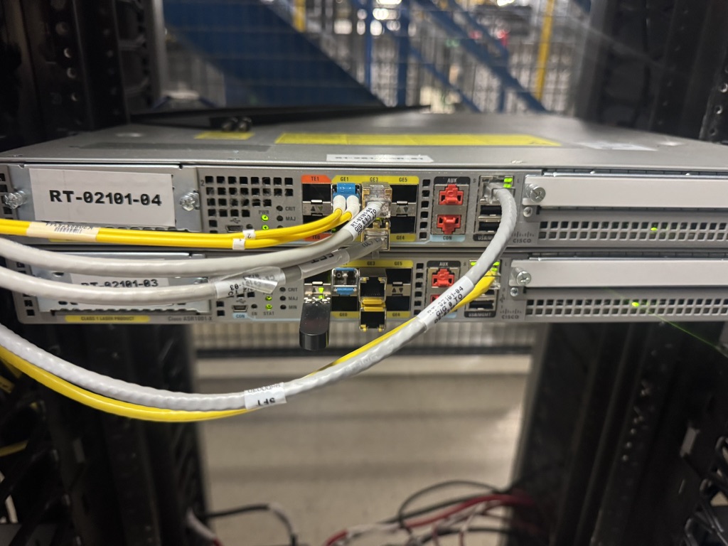
Internet Exchange Points (IXPs) are facilities or infrastructure platforms where networks meet to peer. An IXP is essentially a shared Layer-2 network (LAN) – often one or more Ethernet switches in a colocation facility – that connects routers from many different networks (ASes). Instead of running individual fiber cross-connects between every pair of networks (which would not scale beyond a few peers), participants at an IXP all connect to a common switching fabric. This allows any member’s router to exchange traffic with any other member’s router via the exchange, with only a single physical connection per participant to the exchange fabric.
Put simply, an IXP acts as a neutral meeting point for direct interconnection among many networks. By doing so, IXPs help keep local traffic local – for example, ISPs in one city can exchange traffic there, instead of hauling it to distant cities (which would incur extra transit costs and latency). There are over 1,500 active IXPs worldwide as of 2025, reflecting their importance in the Internet’s infrastructure.
Typical IXP Architecture: At the core, an IXP consists of one or more switches (often high-density Ethernet switches) that create a single broadcast domain (the peering LAN). Participants connect via an Ethernet port at a mutually agreed speed (1G, 10G, 100G, etc.). The IXP assigns each participant an IP address on the peering LAN (usually a public IPv4 /24 and IPv6 /64 are reserved for the IXP). All members’ routers are then one “hop” away across that LAN. BGP is the routing protocol used to exchange reachability information on an IXP – each network sets up BGP sessions with others to announce its prefixes and learn theirs, enabling traffic exchange over the shared fabric.
To join an IXP, a network usually needs to bring a router (or a layer-3 device) to the facility (or connect remotely – discussed later) and purchase a port on the exchange switch. The IXP charges participants (often monthly or annually, scaled by port speed) to cover the costs of running the exchange. In return, the members benefit from potentially many peering opportunities through that one port.
From a business perspective, IXPs are often operated by non-profit associations, cooperatives, or commercial entities. Regardless of ownership model, successful IXPs maintain neutrality and fair access – they are there to facilitate peering, not to favor one network over another. A key point in many IXPs’ policies is that the exchange itself does not carry transit traffic and typically does not sell IP transit; it only provides the switching platform for members to peer. For example, FD-IX emphasizes neutrality (“We do not sell upstream IP transit, and we do not compete with our members” – the exchange’s role is simply to enable interconnection, not become an ISP.
IXP Benefits and the Network Effect
IXPs are great for both technical and economic reasons, helping everyone in the network community. When multiple networks converge at an IXP, it opens up numerous new opportunities for them to connect, making things more efficient for everyone involved. Members can save money by sending traffic directly to each other rather than paying third-party providers. Plus, since data can take shorter routes, everything moves faster and with less delay. For example, a local ISP can get content directly from a nearby provider at the IXP, rather than sending it all the way to a far-off hub. The more people join the IXP, the better it becomes for everyone—every new member means more opportunities to connect and share, which in turn attracts even more participants as the benefits continue to grow. We have seen ISPs with residential customers offload up to 80% of their traffic to a robust IX with many content providers.
IXPs also improve redundancy for a region – if one path fails, networks often have alternate peer routes via the exchange. During events like submarine cable cuts or transit outages, local IXPs have been known to keep intra-regional traffic flowing when otherwise it might have detoured around the globe. In short, a robust IXP can increase a locality’s Internet resilience and quality of service.
IXP Switching and Route Servers
On the technical side, an IXP’s switching fabric is typically a pure Layer-2 domain dedicated to member interconnects. Best practices call for it to be a stable, well-managed Ethernet network with safeguards: e.g. one MAC address per port is enforced to prevent members from accidentally bridging other devices into the LAN STP (Spanning Tree), proxy ARP, and other L2 protocols from member ports are usually disabled or filtered to avoid any L2 loops or hijacks on the shared medium. Essentially, each participant should connect a router (not a switch) to the IXP and treat it as an external network link.
Because a busy exchange can have dozens or hundreds of members, the BGP peering configuration can become a challenge: a full mesh of BGP sessions (each network pairing with every other network) would mean N×(N-1)/2 sessions, which becomes unmanageable at scale. To ease this, most IXPs offer route servers – special routers operated by the IXP that act as a routing information broker. Members can establish a BGP session with the route server(s) and automatically exchange routes with many participants via this one session. The route server reflects routes to other participants, but typically does not forward traffic (it’s not in the data path, only the control path). This arrangement is known as multilateral peering (where all participants agree to share routes via the route server) rather than bilateral peering (direct one-to-one BGP sessions between networks).
Each member is free to use the route server or not. Some large networks prefer bilateral only (for more control over each session), whereas many use the route server for convenience and then optionally set up direct BGP sessions with a handful of major peers as needed. Best practice is to peer with two route servers (most IXPs run at least two for redundancy) so that if one goes down, you still have route updates via the other. The route servers usually have transparent BGP attributes – e.g. they do not alter next-hop – so that traffic goes directly between the peers, not through the server. They also implement comprehensive filtering and enforce any multilateral peering agreements in effect.
For example, FD-IX runs route servers with an open peering policy, so any member can easily connect and start sharing routes with everyone else (it’s a really welcoming, handshake-friendly environment). If your network connects to FD-IX, you just set up BGP with the route server and you’re all set to exchange routes with dozens of other networks—no need for lots of individual negotiations. Of course, you can still set up direct sessions with other members if you’d like! The route servers on FD-IX and most IXPs also help keep things safe by enforcing maximum prefix limits and filtering routes using IRR/RPKI data, ensuring that no one advertises something they shouldn’t. I’ll talk more about filtering later.
Benefits of Peering (Technical and Business)
Why go through the effort of establishing peering at IXPs or via private links? For network engineers and business decision-makers alike, peering can offer substantial advantages:
- Cost Savings: This is often the primary business driver. Exchanging traffic via peering avoids sending it over expensive transit links. Transit contracts typically charge per Mbps or per byte – costs that can add up quickly for large traffic volumes. Peering, especially at an IXP, usually costs only a fixed port fee (and perhaps minimal cross-connect fees), making the marginal cost of additional traffic essentially zero. By “cutting out the middleman,” networks can significantly reduce their overall IP bandwidth bill. FD-IX, for instance, markets peering as a way to “Declare Your Independence from Transit” in its outreach, emphasizing how members can reduce transit costs by offloading traffic to the exchange.
- Improved Performance (Lower Latency & Higher Throughput): Peering often provides more direct routes between networks, which means packets travel fewer hops and shorter distances. The result is typically lower latency and potentially less packet loss or jitter – critical for latency-sensitive applications like video streaming, VoIP, or interactive applications. Because peering links are often higher bandwidth and less congested (networks engineer them for heavy mutual traffic), end-to-end throughput can improve as well. Users get a faster, closer connection to content or services. For example, if a streaming service peers with a broadband ISP in-region, customers of that ISP may experience noticeably better quality and start times since the video traffic doesn’t have to traverse long, slow paths. In short, keeping traffic local improves user experience. Technically, networks can also tweak routing preferences to favor these shorter paths, ensuring the lowest-delay path is taken for peered routes.
- Greater Control over Routing: When you peer directly, you have granular control over what routes you announce to each peer and what routes you accept. This level of control (via BGP policies) allows for fine-tuned traffic engineering (you might prefer sending traffic via one peer over another based on performance or cost, for instance). You aren’t at the mercy of a transit provider’s routing decisions. Also, security-wise, a direct connection limits exposure – fewer networks in between means fewer points where traffic could be intercepted or manipulated. One analysis noted that peering’s direct nature “limits the exposure to potential threats” compared to sending traffic through multiple transit networks. Many networks also like peering because it avoids having a single upstream as a bottleneck – they can route around problems more easily if they have multiple direct interconnects. We at FD-IX have also found networks that peer have increased their overall throughput, which pointed to a bottleneck on their transit provider.
- Capacity and Scaling for High Volume: For networks exchanging massive traffic (think tens of gigabits per second) between each other, peering on a high-capacity port is often more feasible than pushing all that traffic through third-party transit links (which might not only be costly but also congested). Peering relationships can be scaled by upgrading port speeds or adding additional links (link aggregation or multiple ports) relatively easily. While transit services can also scale, the cost to push another 10 Gbps through transit could be substantial, whereas if you already have a 100G peering port with headroom, sending another 10 Gbps to a peer is “free.” Thus, peering is attractive for large content and “eyeball” networks to scale their interconnection.
- Redundancy and Resilience: Establishing peering with multiple networks increases the redundancy of your connectivity. If one transit provider has an outage, some traffic might still flow through peers (assuming the prefixes are available via peers). Likewise, multiple peering points mean alternative paths for traffic if one route is down. Many critical networks pursue both peering and transit from multiple providers to avoid single points of failure. In practice, an IXP can act like a local safety net – if a direct private interconnect (PNI) between two networks fails, they might temporarily rely on the IXP peering fabric to carry that traffic as a backup. Having diverse peering can thus improve uptime and reliability of service delivery.
- Community and Strategic Benefits: This is less technical, but worth noting. Participating in an IXP often puts a network operator in touch with the local network engineering community. It can facilitate cooperation (such as security incident response coordination, or mutual aid during outages). Many IXPs, including FD-IX, host regular member meetings or conferences to share knowledge. There’s also an element of improving the Internet ecosystem – by peering, networks help reduce strain on upstream infrastructure and improve Internet quality for end-users. FD-IX, for example, positions itself as “community-driven” and even offers free 1 Gbps ports to non-profit networks like schools and public libraries to encourage better local connectivity. This kind of initiative demonstrates an understanding that better interconnection benefits everyone (and of course, it doesn’t hurt the IXP to have more participants and traffic, either).
Peering isn’t a one-size-fits-all solution—it has its own unique challenges, such as handling BGP sessions, managing routing policies with numerous partners, or addressing traffic imbalances in agreements. Still, for many, the upsides are worth it, especially as an Internet business grows. These days, success for content providers and ISPs often comes down to having a smart interconnection approach: using peering to save money and boost quality wherever possible, and relying on transit to reach everywhere else.
Types of Peering: Public, Private, and Remote
Not all peering is equal. Network engineers have a few models to choose from when establishing where and how to peer:
Public Peering (IXP Peering)
Public peering refers to peering over a shared IXP fabric, as described earlier. In this scenario, multiple networks converge at a common exchange point (public in the sense of a multi-party environment, although the exchange may be located in a secure data center) to exchange routing information. Each participant likely peers with many others using either bilateral BGP sessions or the IXP’s route server (multilateral). Public peering is cost-effective because a single connection gives access to many networks. It’s ideal for exchanging modest-to-large amounts of traffic with a broad range of networks in one place.
For example, a regional ISP might join a public IXP and instantly be able to exchange traffic with content CDNs, cloud providers, academic networks, and other ISPs present there – all via one port.
The advantages of public peering include efficient one-to-many connectivity and the economic benefit of shared infrastructure (bringing down the average cost).
The Disadvantages might include less control over the environment (since the fabric is shared, issues such as broadcast traffic or congestion on the exchange could affect everyone) and bandwidth limits per peer if the exchange port becomes a bottleneck. In practice, well-run IXPs mitigate these issues by modern equipment and policies, but some very large networks might still prefer direct private links for their largest traffic exchanges to guarantee dedicated capacity.
FD-IX is a good illustration of public peering at work – it provides a multi-party peering fabric across its member data centers, where any of the 55+ participating ASNs can freely peer with each other. Networks like Akamai, Cloudflare, and Hurricane Electric are present at FD-IX and offer public peering, allowing Midwest ISPs to offload traffic locally rather than via upstream transit.
Private Peering (PNIs)
Private peering is when two networks decide to interconnect directly, one-on-one, outside of an exchange. This typically occurs via a dedicated physical link (e.g., a fiber cross-connect in a data center) between the two parties. They will set up a direct BGP session over that link and exchange traffic only between themselves. Private Network Interconnects (PNIs) are often used when traffic volume between two networks is very large, justifying a dedicated connection, or when one/both parties prefer not to share a common fabric for that traffic.
Advantages of private peering include: full control of the link (it’s not shared with others), potential security/privacy benefits, and the ability to handle large capacity (they can turn up multiple 100G links if needed purely for this bilateral exchange). There’s also no concern about a third network congesting the path. Disadvantages include cost (each PNI requires its own ports, optics, cross-connect fees, etc., so it’s only cost-effective if the traffic volume is high enough) and scalability (one link = one peer; if you need to connect to 10 networks privately, that’s 10 separate links to manage).
Many large networks use a hybrid approach: they peer publicly at IXPs with dozens of networks but also have PNIs with certain key partners (usually large content or tier-1 ISPs) where the traffic between just those two is enormous or where they want a direct path for quality reasons. For instance, a big ISP might have a private 100G interconnect with Netflix in a data center to handle Netflix’s traffic, even if both are also on a local IXP. They do it to ensure capacity and reliability for that specific flow.
At FD-IX, in addition to the public exchange, they explicitly support private peering as a service – members colocated in the same facility can set up direct cross-connects, or even across the FD-IX fabric they can establish a dedicated VLAN for private traffic if needed (FD-IX calls this “Private Peering” in their service list)fd-ix.com. In fact, FD-IX’s PeeringDB entry notes that “PNI interconnects are available across the IX fabric”, meaning two members can arrange a dedicated interconnect via the exchange’s infrastructure if they choose peeringdb.com. This is somewhat unique: it implies you could use FD-IX’s presence in multiple sites to facilitate private VLANs between two networks (essentially using the exchange’s transport but segregated from the public VLAN).
Remote Peering
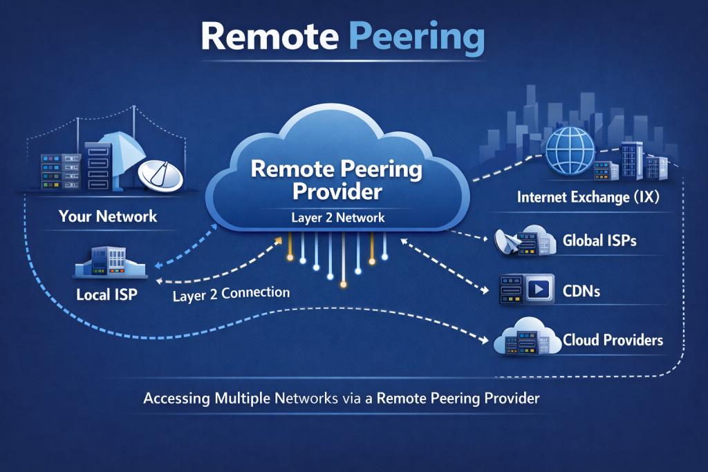
A more recent trend is remote peering, which allows networks to peer at an IXP without physically being present at the exchange’s location. In remote peering, a network uses a carrier or intermediary to extend its reach to the IXP. For example, if Network A is in a city with no local IXP, but they want to peer at an IXP in another city, they could buy a transport circuit to that IXP’s facility or work with a remote peering provider who already has connectivity. The remote provider essentially delivers the network’s traffic into the exchange over a VLAN or tunnel, and the network appears as just another member on the IXP LAN, just as if they had a router in the rack locally.
The obvious benefit of remote peering is avoiding the cost of deploying infrastructure in distant data centers. A network can gain access to multiple exchanges around the world by purchasing remote peering ports from carriers (many carriers and IXP resellers offer this). This can be much faster and cheaper to turn up than building your own presence in each location. For instance, a smaller ISP in one country might remotely peer at major European exchanges (LINX, AMS-IX, DE-CIX, etc.) via a single provider that connects them, rather than setting up routers overseas. It’s a way to quickly broaden peering without a physical footprint.
However, remote peering comes with trade-offs: increased dependency on the transport provider (adding an extra AS in the path, albeit usually just one), and potentially higher latency compared to being on-site (though often still better than not peering at all). There’s also less direct control – if the remote link fails, your connection to the IXP is lost. Networks must carefully consider latency and capacity when using remote peering; generally, it works best when the remote distance isn’t too great or when the cost of a slight latency penalty is outweighed by the peering benefits.
Remote peering has grown popular – studies have shown a significant fraction of members at major IXPs are actually remote participants via Layer2 VPNs and such. Some large content networks even use remote peering to reach secondary IXPs they wouldn’t otherwise bother with, to gather a few extra networks in their coverage. This also allows them redundancy as IXPs become more important to networks.
In summary, public peering equals many-to-many on a shared fabric (efficient and broad), private peering = one-to-one dedicated link (powerful for heavy flows), and remote peering equals peering via an intermediary (extends reach without physical presence). Many networks utilize all three types in different scenarios. For instance, an ISP might do public peering at two IXPs, have private 10G links with a couple of major content providers, and use a remote peering service to reach a third IXP in another region – all simultaneously.
Routing Considerations and Best Practices for Peering
Establishing peering links is one thing; making sure they are used effectively and safely is another. Peering often entails opening up direct BGP sessions with networks that were previously reached via transit, so careful planning of routing policy is required. Here we outline common routing considerations for network engineers when peering:
BGP Session Setup at the IXP
When two networks decide to peer (whether publicly at an IXP or via a private link), they will configure an eBGP session between their routers. Typically, at an IXP, each participant has a unique ASN (Autonomous System Number) and one or more IP addresses on the exchange LAN. Best practice is to use the public ASN (not a private ASN) and IPs provided by the IXP’s assigned block for peering. Peering is done with BGP version 4, exchanging IPv4 and/or IPv6 routes as agreed.
Key details to negotiate or configure for each BGP peering session include:
- Which prefixes will be advertised: Generally, each network advertises the prefixes it originates (and possibly those of its downstream customers, if allowed by the peering policy). Typically, each side should only announce prefixes they are authorized to (their own or their customers’), to avoid acting as transit for the other – remember, in peering, you do not forward third-party routes. For example, if ISP A and ISP B peer, ISP A should not announce routes learned from ISP C (its transit provider) to ISP B, or vice versa, otherwise A or B would unintentionally become a transit provider. Robust route filters (see below) prevent such mistakes.
- BGP attributes: It’s common to set
NEXT_HOPas the original router’s IP (in IXP scenarios, BGP next-hop is typically the originator’s interface on the IXP LAN). Ensure your routers do not rewrite the next-hop when reflecting route-server routes, etc., so traffic goes direct. Also, Multi-hop is usually not needed on a LAN (BGP TTL=1 is often used as a security measure withebgp-multihopdisabled, since peers are single hop away). Many enforce GTSM (Generalized TTL Security Mechanism) with a high TTL to guard against off-subnet spoofing. Using BGP MD5 passwords is another security step for sessions (some IXPs allow you to set an MD5 on bilateral sessions for protection). - ARP/ND and MTU: The exchange point will facilitate L2 adjacency. Make sure to use the correct VLAN if required (most IXPs use a single VLAN for all peering; some may have separate VLANs for IPv6 or other services). Confirm the allowed MTU (1500 bytes is standard on many exchanges, though some support jumbo frames – FD-IX’s peering LAN uses 1500 bytes MTU). Mismatched MTU can cause odd problems (e.g., large BGP OPEN messages not getting through).
- Route Server vs. Direct Peering: Decide whether to peer via the route server. If so, configure a session to the IXP’s route server ASN and IP address. If no, you’ll need to individually coordinate and set up sessions with each desired peer (often via PeeringDB contacts or the IXP member portal). Many do both: use the RS as a baseline for many peers, and add direct sessions for heavy hitters or specific needs. Note that if using direct sessions, both sides must configure filters and policies; with a route server, the RS often assists with filtering.
Once BGP is up, each side should apply import and export policies (preferring peer routes appropriately and filtering as needed). A crucial config on Cisco/Juniper and the like is to ensure no BGP auto-summary or default acceptance, and typically, one does not redistribute IGP or 0.0.0.0/0 into peering. Peering BGP sessions should generally carry only specific customer or content routes, not the full Internet table (in fact, sending a full table to an IXP peer is unnecessary and could violate policy).
Most IXPs encourage members to set max-prefix limits on each peering session. For example, FD-IX recommends setting your BGP max-prefix to allow ~100,000 IPv4 routes and ~75,000 IPv6 routes for their route-server sessions. This limit is slightly above the number of routes you expect; it serves as a safety mechanism to shut down the session if a peer suddenly spews way too many prefixes (which could indicate a leak or error, preventing it from overwhelming your router).
Traffic Engineering for Peering
Having multiple paths (peering and transit, or multiple peers) introduces the opportunity – and necessity – of traffic engineering. Common goals: maximize use of cheaper peering links, balance load across links, and ensure stable, predictable routing. Some considerations:
- Local Preference: A common practice is to set routes learned from peering sessions with a higher local preference than routes learned from transit. This ensures that when both exist, your router prefers the peering route (since it’s cheaper and likely shorter). For instance, an ISP might set
LOCAL_PREF = 200for all routes from IXPs and 100 for routes from transit. This way, if a prefix is available via a peer, it will be chosen over the transit path (assuming no other overriding factors). This is a simple but effective way to offload traffic to peering links whenever possible. - AS Path Prepending and Selective Announcements: For outbound traffic engineering (i.e., incoming traffic to you), you can manipulate what you announce to influence how others route to you. One best practice is to announce more specific routes to IXPs and broader routes to transit. By advertising, say, a /24 prefix at the IXP (the most specific allowed in global routing) while only a /23 covering it to your transit, you ensure that other networks will prefer the /24 via the peer (longer prefix match) for traffic, sending that traffic via the IXP peer. This trick helps attract traffic to the peering link. If leaking specifics isn’t possible, the alternative is AS path prepending: announce your prefixes to transit with prepended AS paths (making them look longer/worse), and announce normally (no prepends) to peers – thus networks will prefer the non-prepended (peer) path. The LACNIC guide recommends exactly this: “send prefixes without prepending to the IXP, and with greater prepending to the IP transit provider”. The general principle: make routes via your peers more preferred (shorter AS paths, higher local-pref on your side, etc.), so traffic flows over peering where possible, reserving transit as a backup or last-resort path. This can be viewed as a heavy-handed approach, but it’s only influencing the IX routing table, not the global routing table.
- Load Balancing Among Peers: If you have multiple peering points or multiple peers providing routes to the same destination, you might need to balance traffic. BGP by itself won’t do per-packet load balance, but you can use traffic engineering techniques. For example, if two peers both can reach a certain prefix, you might use BGP communities or selective advertisements to split prefixes – send half of your more specific routes to one peer, half to the other. Some exchanges or route servers support traffic engineering communities where you can tag routes to indicate preference (e.g., a community that tells the route server to only advertise your route to certain peers). Engineering inbound traffic can be the trickiest; often it involves a combination of selective announcements, prepends, and sometimes community signals to route servers or bilateral peers about how to treat your routes.
- Avoiding Overload and Failover: Ensure that your peering links (and devices) have enough capacity. It’s wise to keep utilization well below 100% so that if another link fails and traffic shifts, the remaining peering link can handle the surge. Also, monitor traffic patterns – if a new popular service starts exchanging traffic via a peer and saturating your port, you may need an upgrade or a direct PNI with that service. Some networks automate detection of when a peer link regularly maxes out, triggering capacity upgrades or policy adjustments.
- Hot-Potato vs Cold-Potato Routing:In peering, each network generally wants to hand off traffic as soon as possible (hot-potato) to the other network’s infrastructure to minimize resource usage. This usually aligns with low latency anyway (closer exit equals shorter path). However, there are cases where you might carry traffic further (cold-potato) before handoff for performance reasons (maybe your network has a faster internal path to reach the peer’s far edge than the peer’s path from a nearer meet point). These are advanced considerations and often involve bilateral agreements – most settlement-free peering assumes hot-potato unless otherwise agreed. In any case, if you operate a global network with multiple peering locations with the same partner, you’ll want to tune BGP to hand off traffic to the right place. Often, this means announcing regionalized routes (e.g., only announce certain local prefixes at the local IXP, so that the peer sends traffic for those prefixes only to that local site, not to a peering site far away).
Effective traffic engineering for peering involves preferring peers over transit (for cost/latency), sending traffic to peers at the closest opportunity, and advertising prefixes in a way that peers will prefer the peering path into your network. Done right, this can significantly optimize performance and cost. But it requires diligent planning and monitoring, as changes in network conditions or routing in the wild can upset the balance, necessitating adjustments.
Route Filtering and Security
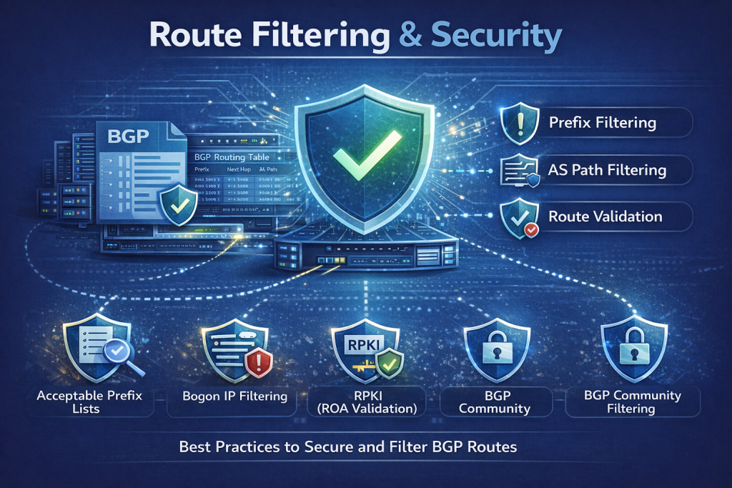
Opening up BGP peering introduces some security considerations. Without proper filters, a bad actor or a misconfigured router at a peer could announce incorrect routes (whether accidentally or maliciously), potentially leading to traffic hijacks or route leaks. Thus,stringent route filtering is essential on all peering sessions:
- Import Filtering (from peers): Generally, you want to accept only valid routes that a peer is authorized to send. This usually means filtering by prefix and AS. Many networks use IRR (Internet Routing Registry) data to build prefix filters for each peer – e.g., require that each route a peer sends matches a route object in an IRR database listing that peer’s ASN as origin. Increasingly, RPKI validation is also used: if a peer announces a prefix that fails RPKI (no valid ROA or a mismatched origin AS or too long prefix), you reject it. According to industry studies, “the vast majority of IXPs implement filtering using RPKI and/or IRR” on their route servers, which significantly reduces the risk of hijacks being propagated via the exchange. If you’re peering bilaterally, you should apply similar filters on your router. At minimum, filter out:
- Bogons and Martians: Never accept private or reserved prefixes, default routes, or the IXP LAN prefix itself from a peer. Many IXPs explicitly require members to not announce RFC1918 space, default routes, etc., and route servers will drop those.
- Overly Specific Prefixes: Often, exchanges set a limit like no IPv4 prefix longer than /24, no IPv6 longer than /48. This prevents route table bloat and weird de-aggregations.
- Max Prefix: As mentioned, configure max-prefix limits per peer. If a peer normally sends you ~5,000 routes, set a threshold maybe 20% higher; if suddenly 50,000 routes come in due to a leak, your router will shut the session, protecting your FIB.
- AS Path sanity: Filter routes with your own AS in the path (to avoid loops), excessively long AS paths (often indicate something wrong), or private ASNs in the path (unless explicitly allowed).
- Optionally, policy-based filters: If a peer is not supposed to transit you traffic, ensure you don’t accept routes with third-party ASes (this is usually covered by prefix filters, since you only accept their own prefixes anyway).
- Bogons and Martians: Never accept private or reserved prefixes, default routes, or the IXP LAN prefix itself from a peer. Many IXPs explicitly require members to not announce RFC1918 space, default routes, etc., and route servers will drop those.
- Export Filtering (to peers): Similarly, you should only announce to a peer the prefixes that you want them to carry. Usually, that’s only your own prefixes and those of your downstream customers. You should not announce prefixes from one peer to another (to avoid unintended transit). If you buy transit from ISP X, do not export ISP X’s routes to a peer at the exchange! Basic export policy often is: if route is learned from a peer, don’t re-advertise to another peer (no “transit across the IXP”). Route servers enforce this by default – they do not redistribute one peer’s routes to another if the peering is supposed to be bilateral only (unless both are route-server clients and policy allows it). On your own BGP, you might use communities or separate RIBs to ensure routing domain isolation.
- Many networks tag their routes (e.g., customer routes vs. own vs. transit) so they can cleanly filter what goes out to peers.
- A practical tip: Use BGP communities or peer-specific route-maps to mark which routes should go to which peer. For instance, send more specific routes or only a subset of routes to certain peers if needed for TE.
- Route Server Filtering: If using an IXP’s route server, know that the route server typically performs IRR/RPKI filtering on all clients’ routes, and often implements prefix origin validation. For example, if you peer via route server at FD-IX, the route server will drop any BGP announcement from you that doesn’t match the prefixes in your PeeringDB/IRR entries or is RPKI invalid, thereby protecting other members from a misconfig on your side (and vice versa). Route servers also often support BGP communities that let you opt-out of sending to certain peers (e.g., if you don’t want to peer with a particular network, you can set a community on your prefix that the RS interprets to not advertise it to that AS).
- Security Enhancements: Employ BGP security features, as mentioned: GTSM (setting TTL=255 on eBGP with expectation of 254 from a one-hop neighbor can prevent off-path injection), and MD5 session passwords. While these won’t stop route hijacks, they can stop spoofed session attacks or hijacking of BGP sessions themselves. Also, ensure infrastructure protection – e.g., filter traffic to your BGP port so only the expected peer IP can talk to it, etc.
- MANRS and Best Practices: There are community initiatives like MANRS (Mutually Agreed Norms for Routing Security) which encourage operators to do all the above – filtering, anti-spoofing, address validation. Many IXPs are MANRS participants and require members to adhere to these guidelines. FD-IX indicates a commitment to such security measures, noting plans for deeper participation in RPKI and MANRS to improve routing security on the exchange.
The takeaway: Never trust blindly in BGP – always filter. A significant portion of Internet incidents (route leaks, hijacks) have been due to missing filters. By implementing strict filters at IXPs, one can prevent mistakes from cascading. And in a multi-lateral environment, a mistake by one peer could affect many, so IXPs and members collectively maintain a robust filtering regime.
As a final point, it’s wise to monitor your peering sessions. Use BGP monitoring tools or services (such as route collectors or BMP feeds) to see what routes you’re receiving and advertising. Many IXPs publish a route server looking glass or data feed. Keeping an eye on changes can help you quickly identify if a peer suddenly does something unexpected (like starts announcing a full table or your own prefix back to you). Automation and alerting on BGP anomalies is increasingly part of good operational hygiene for network engineers engaged in peering.
Conclusion
Interconnection is the lifeblood of the Internet, and understanding its forms – peering and transit – is crucial for network engineers looking to optimize performance and costs. Peering allows networks to exchange traffic directly for mutual benefit, improving latency and saving transit fees, while transit provides the universal connectivity that fills in the gaps, ensuring every destination can be reached even without a direct peer. Internet Exchange Points serve as the physical and logical hubs that enable large-scale peering, multiplying connections between networks and amplifying the Internet’s resilience and efficiency.
We see that a well-run IXP (like FD-IX in the Midwest) combines the right technical architecture – robust switching fabric, route servers, distributed reach – with policies and services that encourage broad participation. The result is that content providers get closer to users, ISPs reduce upstream costs, and users experience a faster, smoother Internet.
From a technical standpoint, engaging in peering requires careful BGP routing practices: setting up sessions, engineering traffic with local preference or more specific routes, and – vitally – filtering routes to keep the Internet secure and stable. The effort is well worth it. By keeping traffic local and building direct connections between networks, peering via IXPs can dramatically improve network performance and reduce reliance on any single transit provider.
In today’s world of ever-increasing traffic (thanks to video streaming, cloud services, and more), efficient interconnection is more important than ever. The trends are clear: more networks are peering, new IXPs are popping up (over 1,500 globally, according to pulse.internetsociety.org), and technologies like SDN and automation are making interconnection provisioning faster. As 5G and AI expand, we can expect even more demand for local peering to handle data closer to where it’s produced and consumed.
For network engineers, staying on top of interconnection strategy – when to peer, where to peer, how to engineer those sessions – will remain a key part of the job. The bottom line: smart peering and IXP usage can deliver substantial technical and business gains, from lower latency for users to lower costs for operators. In the end, the Internet is a cooperative endeavor, and peering at IXPs embodies that spirit – networks working together to improve connectivity for everyone.
j2networks family of siteshttps://j2sw.com
https://startawisp.info
https://indycolo.net
#packetsdownrange #routethelight
Discover more from Justin Wilson (j2sw)
Subscribe to get the latest posts sent to your email.