Alta Labs just added dynamic routing support to the Route10. This includes BGP. The Route10 uses an FRR-style configuration shell for BGP, so the syntax feels familiar if you have worked with Free Range Routing before. This does not turn the Route10 into a full-table edge router, but it does make it useful for BGP deployments. This is perfect for the Enterprise with your own IP space where redunancy is needed.
Below are some configuration snippets for configuring BGP on this Route 10.
In this example, I am using private ASNs on both sides of the BGP session. The Route10 uses ASN 65010. The upstream or test peer uses ASN 65020. The Route10 advertises 198.51.100.0/24, which is a documentation prefix used here as a safe example. As always, replace with your own values.
The point-to-point handoff can use a /31 if the interface addressing supports it. That is common on router-to-router links because it avoids wasting two addresses on a network and a broadcast address. If you want the safer option, use a /30 and assign one usable IP to each side.
Here is the /31 example.
Route10 local IP: 203.0.113.0/31
Peer IP:          203.0.113.1/31
Route10 ASN:      65010
Peer ASN:         65020
dvertised route: 198.51.100.0/24
Inbound community: 100:100
Where to Configure BGP on the Route10
The Route10 handles BGP differently than many traditional routers. There is no series of forms where you enter neighbors, route maps, and prefix lists. Instead, Alta Labs provides access to an FRR configuration shell directly from the management interface.
From the Route10 web interface, navigate to:
Settings → Networks → Routes → Dynamic Routing
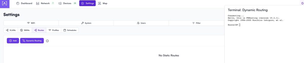
You will see an FRR terminal window. This is where the BGP configuration is entered. If you have experience with Cisco IOS, Arista EOS, VyOS, Cumulus Linux, or FRRouting, the commands will feel familiar.
I recommend configuring the IP addressing on the interface first. Verify that the Route10 can ping the far-end router before attempting to establish BGP. A surprising number of BGP troubleshooting sessions turn out to be basic Layer 3 reachability problems.
Once the interface addresses are configured and connectivity is working, paste the BGP configuration into the FRR terminal. After entering the configuration, exit the terminal and save the changes when prompted. The Route10 will then apply the configuration and attempt to establish the BGP session.
You can verify operation from the same FRR terminal using commands such as:
show ip bgp summary
show ip bgp neighbors
show ip route bgp
The first command confirms whether the BGP session is established. The second provides detailed information about the peer. The third shows routes learned through BGP and confirms that the routing process is installing them into the routing table.
The Route10 BGP configuration would look like this:
configure

ip route 198.51.100.0/24 Null0
ip prefix-list PL-OUT seq 10 permit 198.51.100.0/24
ip prefix-list PL-IN seq 10 permit 0.0.0.0/0 le 32

route-map RM-IN permit 10
match ip address prefix-list PL-IN
set community 100:100 additive
exit

route-map RM-OUT permit 10
match ip address prefix-list PL-OUT
exit

router bgp 65010
bgp router-id 198.51.100.1
neighbor 203.0.113.1 remote-as 65020
!
address-family ipv4 unicast
network 198.51.100.0/24
neighbor 203.0.113.1 route-map RM-IN in
neighbor 203.0.113.1 route-map RM-OUT out
exit-address-family
end
The static route to Null0 matters. FRR will not advertise a prefix from a network statement unless that exact prefix already exists in the routing table. The Null0 route gives BGP a local route to originate without needing a real downstream interface for the lab prefix.
The outbound policy only permits 198.51.100.0/24. Anything else fails the route-map match and is denied by default. You do not need an explicit deny-all statement at the end because the route-map already has an implicit deny when applied to a BGP neighbor.
The inbound policy accepts received IPv4 routes and tags them with community 100:100. The additive keyword keeps any communities already attached to the route. Without additive, the router may replace the existing community set instead of appending to it.
If you prefer a /30 handoff.
Route10 local IP: 203.0.113.1/30
Peer IP:          203.0.113.2/30
The neighbor line changes to this:
neighbor 203.0.113.2 remote-as 65020
The address-family section also needs the updated peer address:
address-family ipv4 unicast
 network 198.51.100.0/24
 neighbor 203.0.113.2 route-map RM-IN in
 neighbor 203.0.113.2 route-map RM-OUT out
exit-address-family
After the config is loaded, check the session state first.
show ip bgp neighbors
Then check what the Route10 is sending to the peer.
show ip bgp neighbors 203.0.113.1 advertised-routes
If you used the /30 example, replace the neighbor address with 203.0.113.2. The advertised route output should show only 198.51.100.0/24. If the prefix does not show up, check that the Null0 route exists and that the prefix-list matches the exact route.
The inbound side can be checked from the BGP table.
show ip bgp
Received routes should show the 100:100 community after the route-map is applied. That proves the Route10 accepted the route and marked it on import. This gives you a clean lab setup for testing Route10 BGP behavior without leaking real production prefixes.
j2networks family of siteshttps://j2sw.com
https://startawisp.info
https://indycolo.net
#packetsdownrange #routethelight
Discover more from Justin Wilson (j2sw)
Subscribe to get the latest posts sent to your email.